

product
We provide you with a one-stop service for a massive selection of electronic components


Problem research and diagnosis
Desk research, in-depth investigation of customer needs, benchmarking against customer competitors, providing customized services

Requirement assessment analysis
Utilize professional tools and models to present the characteristics of customer project requirements in a clear and systematic manner, and provide professional advice and methods

Effect tracking evaluation
Follow up, evaluate, and assess the effectiveness of the project, identify weak areas, help clients improve, and improve the final results

Product Quality Assurance
Satisfy customers' expectations and requirements for product physical quality, with factory control standards superior to domestic and international standards

Industry coverage
We provide professional and ultimate services to over 100 industries upstream and downstream, allowing customers to enjoy the most comprehensive product experience.

Ultimate Customer Service
Strict quality process control ensures contract delivery cycle, timely quality tracking, and timely handling of quality objections. Provide customers with the safest and most technologically advanced pre-sales, in sales, and after-sales services.

Professional technical support
We provide professional product technical support to our customers to ensure they have no worries

Provide customers with
Provide customers with follow-up inventory and project follow-up, comprehensively grasp the details of project progress
real-time info
A comprehensive overview of information, trends, and policies in the electronic components industry, controlling the world and providing a clear view
Main Application Fields of the ISO1050DUBR Driver
2024-11-28
586
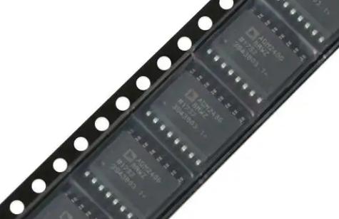
Analysis of Market Demand for Digital Isolator ADM2582EBRWZ
2026-01-18
554
ELITE TEAM
Industry professional elite team, providing you with ultimate service

Dusibibe

Anthony Austin

Alfred Ben

William Jefferson

