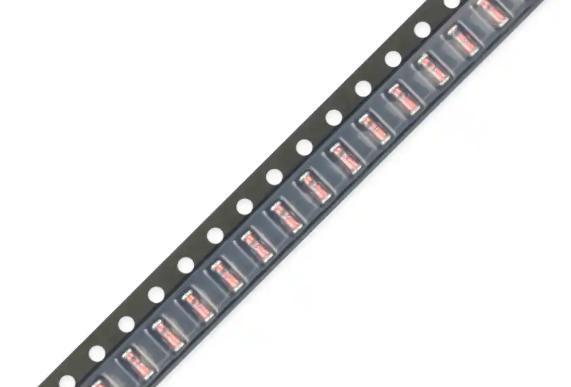
application development in Capacitor Networks, Arrays for CFR-25JB-52-1R: key technologies and success stories
Application Development in Capacitor Networks and Arrays: Key Technologies and Success StoriesCapacitor networks and arrays are fundamental components in electronic systems, playing crucial roles in power management, signal processing, and filtering. While the CFR-25JB-52-1R is a specific resistor model, the broader context of capacitor networks and arrays encompasses various technologies and applications. Below, we explore key technologies related to capacitor networks and arrays, along with notable success stories in application development. Key Technologies in Capacitor Networks and Arrays1. Capacitor Types2. Network Topologies3. Simulation and Modeling Tools4. Integrated Capacitor Arrays5. Power Management ICs6. High-Frequency Applications1. Consumer Electronics2. Automotive Applications3. Telecommunications4. Medical Devices5. Renewable Energy Systems Success Stories in Application Development ConclusionCapacitor networks and arrays are integral to modern electronic design, enabling advancements across various industries. The combination of different capacitor types, innovative network configurations, and integration with other technologies has led to significant improvements in performance, efficiency, and reliability. As technology continues to evolve, the role of capacitors in electronic applications will only become more critical, driving further innovation and success stories in application development. The ongoing advancements in capacitor technology will continue to shape the future of electronics, making them indispensable in the quest for more efficient and compact electronic systems.
2025-04-24 00:38:05
0
CFR-25JB-52-1M Specialized Resistors highlighting the core functional technology articles and application development cases of Specialized Resistors that are effective.
CFR-25JB-52-1M Specialized Resistors: Core Functional Technology and Application DevelopmentOverview of CFR-25JB-52-1M Specialized Resistors The CFR-25JB-52-1M is a specialized resistor designed for high precision and reliability across various electronic applications. These resistors are essential in circuits where accurate resistance values are critical, such as in signal processing, power management, and sensor applications. Their robust design and performance characteristics make them a preferred choice in many industries. Core Functional Technology1. Material Composition2. Precision Tolerance3. Temperature Coefficient4. Power Rating5. Size and Form Factor1. Consumer Electronics2. Automotive Applications3. Industrial Automation4. Medical Devices5. Telecommunications Application Development Cases ConclusionThe CFR-25JB-52-1M specialized resistors highlight the importance of precision and reliability in modern electronic applications. Their advanced material composition, precision tolerances, and robust performance characteristics make them suitable for a wide range of applications, from consumer electronics to critical medical devices. As technology continues to advance, the demand for high-performance resistors like the CFR-25JB-52-1M will only grow, driving further innovation in resistor technology and application development. The continued evolution of these components will play a significant role in enhancing the performance and reliability of electronic systems across various industries.
2025-04-23 01:04:04
0
application development in Chassis Mount Resistors for CFR-50JB-52-1M: key technologies and success stories
Application Development in Chassis Mount Resistors for CFR-50JB-52-1M: Key Technologies and Success StoriesChassis mount resistors, such as the CFR-50JB-52-1M, play a crucial role in various electronic applications by providing reliable resistance in circuits. The development and application of these resistors involve several key technologies and methodologies. Below is an overview of the key technologies and some notable success stories related to chassis mount resistors like the CFR-50JB-52-1M. Key Technologies1. Material Science2. Manufacturing Techniques3. Thermal Management4. Testing and Quality Assurance5. Design Integration1. Telecommunications2. Automotive Applications3. Industrial Automation4. Consumer Electronics5. Renewable Energy Success Stories ConclusionThe development and application of chassis mount resistors like the CFR-50JB-52-1M involve a combination of advanced materials, manufacturing techniques, and rigorous testing protocols. Their successful integration into various industries, including telecommunications, automotive, industrial automation, consumer electronics, and renewable energy, highlights their versatility and importance in modern electronic systems. As technology continues to evolve, the demand for high-performance resistors will likely grow, driving further innovations in this field. The ongoing advancements in material science and manufacturing processes will continue to enhance the capabilities and applications of chassis mount resistors, ensuring their relevance in future electronic designs.
2025-04-22 00:38:04
0
MM74HC4049N Through Hole Resistors highlighting the core functional technology articles and application development cases of Through Hole Resistors that are effective.
Core Functional Technology of Through-Hole Resistors1. Basic Functionality: Through-hole resistors are passive components that limit current flow in electronic circuits. They are essential for controlling voltage levels, dividing voltages, and providing biasing in various applications. Their resistance values, measured in ohms (Ω), dictate how much current can flow through them according to Ohm's Law (V = IR). 2. Construction: These resistors are typically cylindrical with two leads that are inserted into holes on a printed circuit board (PCB) and soldered in place. This through-hole design provides mechanical stability, making them suitable for prototyping, educational projects, and low-volume production runs. 3. Types of Resistors Through-hole resistors come in several types, each suited for different applications:4. Power Rating: Through-hole resistors are available in various power ratings, typically ranging from 1/8W to several watts. This allows designers to select resistors that can handle the expected current without exceeding their thermal limits. 5. Tolerance: Resistors come with different tolerance levels, indicating the permissible variation from the stated resistance value. Common tolerances include ±1%, ±5%, and ±10%, which are crucial for applications requiring precise resistance values. Application Development Cases1. Signal Conditioning: In digital circuits utilizing the MM74HC4049N hex inverter, through-hole resistors can be employed to create voltage dividers or pull-up/pull-down configurations. For instance, when interfacing a sensor output with the inverter, resistors can condition the signal to ensure it meets the required logic levels, enhancing reliability in digital communication. 2. LED Drivers: When using the MM74HC4049N to drive LEDs, through-hole resistors are critical for current limiting. By calculating the appropriate resistor value using Ohm's Law, designers can ensure that the LED operates within its safe current range, preventing damage and ensuring longevity. 3. Oscillator Circuits: Through-hole resistors can be integrated with capacitors to form RC timing circuits. For example, in designing an oscillator circuit with the MM74HC4049N, resistors can determine the frequency of oscillation by controlling the charge and discharge times of the capacitors, allowing for precise timing applications. 4. Level Shifting: In mixed-voltage systems, through-hole resistors can facilitate level shifting. For instance, if the MM74HC4049N is interfacing with a 5V logic level and a 3.3V device, resistors can help adjust the voltage levels appropriately, ensuring compatibility between different logic families. 5. Feedback Networks: In applications where the MM74HC4049N is used in feedback loops (such as in amplifiers or oscillators), through-hole resistors can be utilized to set gain or stability parameters. This ensures that the circuit operates as intended, providing the desired performance characteristics. ConclusionThrough-hole resistors are integral components in electronic design, particularly when used in conjunction with devices like the MM74HC4049N hex inverter. Their robust construction, ease of use, and versatility make them ideal for prototyping and low-volume production. Understanding their functionality and applications can significantly enhance circuit design, performance, and reliability in various electronic projects.
2025-04-21 00:44:03
0
application development in Resistor Networks, Arrays for CFR-25JB-52-1K: key technologies and success stories
2025-04-20 00:44:03
0
CFR-50JB-52-1K Integrated Circuits (ICs) highlighting the core functional technology articles and application development cases of Integrated Circuits (ICs) that are effective.
Overview of CFR-50JB-52-1K Integrated Circuit (IC)The CFR-50JB-52-1K is a specific type of integrated circuit that may not be widely recognized in general literature. However, it is essential to understand its context within the broader landscape of integrated circuits. Below, we will explore the core functional technologies of integrated circuits, including potential applications and development cases that highlight their effectiveness. Core Functional Technologies of Integrated Circuits (ICs)1. Digital Logic Circuits2. Analog Circuits3. Mixed-Signal Circuits4. Power Management ICs (PMICs)5. Radio-Frequency Integrated Circuits (RFICs)1. Consumer Electronics2. Automotive Industry3. Healthcare Devices4. Industrial Automation5. Internet of Things (IoT) Application Development Cases ConclusionIntegrated circuits, including specific types like the CFR-50JB-52-1K, are foundational to modern electronics, enabling a wide range of applications across various industries. The continuous advancement in IC technology, including miniaturization, increased functionality, and improved power efficiency, drives innovation and enhances the effectiveness of electronic systems. As new applications emerge, the role of ICs will only become more critical in shaping the future of technology. For specific details about the CFR-50JB-52-1K, including its specifications, features, and potential applications, consulting the manufacturer's datasheet or technical documentation would provide the most accurate and relevant information.
2025-04-19 12:44:03
1
application development in Sensors, Transducers for MM74HC4050N: key technologies and success stories
2025-04-18 00:44:03
1
CFR-50JB-52-1R Discrete Semiconductor Products highlighting the core functional technology articles and application development cases of Discrete Semiconductor Products that are effective.
2025-04-17 00:44:04
1
application development in Crystals, Oscillators, Resonators for ECS-F1HE155K: key technologies and success stories
Application Development in Crystals, Oscillators, and Resonators for ECS-F1HE155K: Key Technologies and Success StoriesThe ECS-F1HE155K crystal oscillator is a pivotal component in the realm of electronic applications, providing stable frequency references essential for timing in a diverse array of devices. This overview delves into the key technologies that underpin the ECS-F1HE155K and highlights notable success stories that illustrate its impact across various industries. Key Technologies1. High-Frequency Stability 2. Low Power Consumption 3. Miniaturization 4. Temperature Compensation 5. Integration with Other Components 6. Digital Control and Calibration 1. Consumer Electronics 2. Telecommunications 3. Automotive Applications 4. Industrial Automation 5. Medical Devices Success Stories ConclusionThe ECS-F1HE155K crystal oscillator represents significant advancements in crystal technology, enabling a wide range of applications across various industries. Its high-frequency stability, low power consumption, and compact design make it a preferred choice for modern electronic devices. As technology continues to evolve, the demand for reliable and efficient oscillators like the ECS-F1HE155K is expected to grow, driving further innovation and application development in this critical field. The success stories across consumer electronics, telecommunications, automotive, industrial automation, and medical devices underscore the oscillator's versatility and importance in contemporary technology.
2025-04-16 00:38:07
1
ECS-F1HE335K Transformers highlighting the core functional technology articles and application development cases of Transformers that are effective.
2025-04-15 06:50:02
2
application development in Potentiometers, Variable Resistors for ECS-F1HE475K: key technologies and success stories
2025-04-14 18:50:03
2
ECS-F1CE225K Inductors, Coils, Chokes highlighting the core functional technology articles and application development cases of Inductors, Coils, Chokes that are effective.
2025-04-14 07:14:05
1
application development in Capacitors for CFR-12JB-52-110R: key technologies and success stories
2025-04-12 23:44:03
1
S6008L Resistors highlighting the core functional technology articles and application development cases of Resistors that are effective.
Overview of S6008L Resistors and Their Applications The S6008L resistors are a specific type of resistor that can be utilized in various electronic applications. While detailed articles or case studies specifically on the S6008L model may not be readily available, we can explore the core functional technology of resistors in general and highlight common application development cases where resistors, including the S6008L, play a critical role. Core Functional Technology of Resistors 1. **Basic Functionality**: Resistors are passive components that limit the flow of electric current in a circuit. They are essential for controlling voltage and current levels, ensuring that electronic devices operate within safe parameters. 2. **Types of Resistors**: - **Fixed Resistors**: These have a constant resistance value and are widely used in various applications. - **Variable Resistors**: These allow for adjustable resistance, such as potentiometers and rheostats, enabling fine-tuning of circuit parameters. - **Specialty Resistors**: This category includes thermistors (temperature-sensitive), photoresistors (light-sensitive), and others designed for specific applications. 3. **Material Composition**: Resistors can be made from materials like carbon, metal film, and wire-wound materials. The choice of material affects performance characteristics such as stability, temperature coefficient, and power handling. 4. **Power Rating**: Each resistor has a power rating, typically measured in watts (W), indicating the maximum power it can dissipate without overheating. This is crucial for ensuring reliability in circuit designs. 5. **Tolerance**: This specification indicates the allowable variation from the stated resistance value, expressed as a percentage. Lower tolerance values indicate higher precision, which is important in sensitive applications. 6. **Temperature Coefficient**: This measures how much the resistance changes with temperature, which is vital for applications requiring stable performance across varying environmental conditions. Application Development Cases 1. **Voltage Dividers**: Resistors are often used in voltage divider circuits to produce a specific output voltage that is a fraction of the input voltage. This is essential in sensor applications where a specific voltage level is needed for further processing. 2. **Current Limiting**: In LED circuits, resistors are used to limit the current flowing through the LED, preventing damage and ensuring proper brightness. This is a fundamental application in consumer electronics. 3. **Signal Conditioning**: In analog circuits, resistors are used in conjunction with capacitors and inductors to filter signals, shape waveforms, and stabilize feedback loops in amplifiers. 4. **Pull-Up and Pull-Down Resistors**: In digital circuits, resistors are used to ensure that inputs to logic gates are at defined logic levels when no active devices are driving the inputs. This is crucial for reliable operation in microcontroller applications. 5. **Temperature Sensing**: Thermistors, a type of resistor, are used in temperature sensing applications. They change resistance with temperature, allowing for precise temperature measurements in HVAC systems, automotive applications, and consumer electronics. 6. **Power Supply Regulation**: Resistors are used in power supply circuits to help regulate voltage levels and ensure stable operation of electronic devices. They can be part of feedback loops in voltage regulators. 7. **Audio Applications**: In audio circuits, resistors are used to control gain, set bias points, and filter signals. They play a critical role in ensuring high-quality sound reproduction in amplifiers and mixers. Conclusion Resistors, including specific models like the S6008L, are fundamental components in electronic design and application development. Their versatility allows them to be used in a wide range of applications, from simple current limiting to complex signal processing. Understanding their core functionalities and applications is essential for engineers and designers working in electronics. For specific articles or case studies, it would be beneficial to consult technical journals, manufacturer datasheets, or industry publications that focus on electronic components and circuit design. By leveraging the unique characteristics of the S6008L resistors, engineers can enhance the performance and reliability of their electronic designs across various applications.
2025-04-12 05:28:02
1
What is the working principle of inductor inductance?
What is the Working Principle of Inductor Inductance? I. Introduction Inductors are fundamental components in electrical engineering, playing a crucial role in various applications, from power supplies to radio frequency circuits. An inductor is a passive electrical component that stores energy in a magnetic field when electric current flows through it. The property of an inductor that quantifies its ability to store this energy is known as inductance. Understanding the working principle of inductance is essential for engineers and technicians alike, as it influences the design and functionality of many electronic devices. This article will delve into the basic concepts of inductance, the working principles of inductors, their behavior in circuits, applications, and the factors affecting their performance. II. Basic Concepts of Inductance A. Definition of Inductance Inductance is defined as the property of an electrical conductor that opposes a change in current. When the current flowing through an inductor changes, it induces a voltage in the opposite direction, according to Lenz's Law. This property is measured in henries (H), named after the American scientist Joseph Henry, who made significant contributions to the field of electromagnetism. B. Historical Background The concept of inductance emerged in the 19th century, primarily through the work of Michael Faraday and Joseph Henry. Faraday's experiments with electromagnetic induction laid the groundwork for understanding how changing magnetic fields can induce electric currents. Henry's work further explored the relationship between current and magnetic fields, leading to the formal definition of inductance. C. Units of Inductance (Henry) The henry is the SI unit of inductance. One henry is defined as the inductance of a circuit in which a change in current of one ampere per second induces a voltage of one volt. This unit provides a quantitative measure of an inductor's ability to store energy in a magnetic field. D. Relationship Between Current and Magnetic Field The relationship between current and magnetic field is fundamental to understanding inductance. When current flows through a conductor, it generates a magnetic field around it. The strength of this magnetic field is proportional to the amount of current flowing through the conductor. In an inductor, this magnetic field is concentrated and can store energy, which is released when the current changes. III. The Working Principle of Inductors A. Electromagnetic Induction 1. Faraday’s Law of Electromagnetic Induction Faraday's Law states that a change in the magnetic field within a closed loop induces an electromotive force (EMF) in the loop. This principle is the foundation of how inductors operate. When the current through an inductor changes, the magnetic field around it also changes, inducing a voltage that opposes the change in current. 2. Lenz’s Law Lenz's Law complements Faraday's Law by stating that the direction of the induced EMF will always oppose the change in current that created it. This opposition is what gives inductors their unique behavior in circuits, as they resist sudden changes in current. B. Construction of an Inductor 1. Core Materials (Air, Ferrite, Iron) Inductors can be constructed using various core materials, which significantly affect their inductance. Air-core inductors use no magnetic material, while ferrite and iron cores enhance the magnetic field, increasing inductance. The choice of core material depends on the application and desired inductance. 2. Wire Winding The wire used in an inductor is typically copper due to its excellent conductivity. The number of turns in the wire winding also influences inductance; more turns result in higher inductance. The arrangement and spacing of the wire can also affect the inductor's performance. C. Inductance Formula 1. Self-Inductance Self-inductance refers to the inductance of a single coil. The formula for self-inductance (L) is given by: \[ L = \frac{N^2 \cdot \mu \cdot A}{l} \] where: - \( N \) = number of turns - \( \mu \) = permeability of the core material - \( A \) = cross-sectional area of the coil - \( l \) = length of the coil 2. Mutual Inductance Mutual inductance occurs between two coils when the magnetic field of one coil induces a voltage in another. The formula for mutual inductance (M) is similar to that of self-inductance and is influenced by the same factors. IV. Behavior of Inductors in Circuits A. Inductive Reactance 1. Definition and Formula Inductive reactance (X_L) is the opposition that an inductor presents to alternating current (AC). It is given by the formula: \[ X_L = 2\pi f L \] where: - \( f \) = frequency of the AC signal - \( L \) = inductance in henries 2. Frequency Dependence Inductive reactance increases with frequency, meaning that inductors will oppose higher frequency signals more than lower frequency signals. This property is utilized in filtering applications. B. Time Constant in RL Circuits 1. Charging and Discharging of Inductors In an RL circuit (a circuit with a resistor and an inductor), the time it takes for the current to reach its maximum value when a voltage is applied is determined by the inductance and resistance. The inductor resists changes in current, leading to a gradual increase in current. 2. Time Constant Formula The time constant (τ) for an RL circuit is given by: \[ \tau = \frac{L}{R} \] where: - \( R \) = resistance in ohms This time constant indicates how quickly the inductor responds to changes in current. C. Energy Storage in Inductors 1. Magnetic Field Energy Inductors store energy in the magnetic field created by the current flowing through them. This energy can be released back into the circuit when the current decreases. 2. Energy Storage Formula The energy (W) stored in an inductor is given by the formula: \[ W = \frac{1}{2} L I^2 \] where: - \( I \) = current through the inductor This formula highlights the relationship between inductance, current, and energy storage. V. Applications of Inductors A. Power Supply Circuits Inductors are commonly used in power supply circuits to smooth out voltage fluctuations and filter out noise. They help maintain a stable output voltage by storing energy during periods of high demand. B. Filters and Oscillators Inductors are integral components in filters and oscillators, where they work in conjunction with capacitors to create resonant circuits. These circuits can selectively allow certain frequencies to pass while blocking others. C. Transformers Transformers, which are used to step up or step down voltage levels, rely on mutual inductance between coils. The primary coil creates a magnetic field that induces a voltage in the secondary coil. D. Inductive Sensors Inductive sensors utilize the principles of inductance to detect the presence of metallic objects. These sensors are widely used in industrial applications for proximity detection and automation. VI. Factors Affecting Inductance A. Number of Turns in the Coil The inductance of a coil increases with the number of turns. More turns create a stronger magnetic field, enhancing the inductor's ability to store energy. B. Core Material and Geometry The choice of core material significantly impacts inductance. Materials with high permeability, such as ferrite and iron, increase inductance compared to air. The geometry of the core also plays a role; for instance, a larger cross-sectional area can enhance inductance. C. Coil Dimensions (Length and Diameter) The dimensions of the coil affect its inductance. A longer coil with a smaller diameter generally has lower inductance than a shorter, wider coil, due to the distribution of the magnetic field. D. Frequency of Operation The frequency of the AC signal affects inductive reactance and, consequently, the overall behavior of the inductor in a circuit. Higher frequencies lead to greater reactance, influencing circuit design. VII. Limitations and Challenges A. Parasitic Capacitance Inductors can exhibit parasitic capacitance, which can affect their performance at high frequencies. This unintended capacitance can lead to resonance and signal distortion. B. Saturation of Core Material When the magnetic field in an inductor exceeds a certain threshold, the core material can become saturated, leading to a decrease in inductance and potential overheating. C. Losses in Inductors (Copper Loss, Core Loss) Inductors are not without losses. Copper loss occurs due to the resistance of the wire, while core loss arises from hysteresis and eddy currents in the core material. These losses can reduce efficiency and performance. VIII. Conclusion In summary, inductors are vital components in electrical engineering, with their ability to store energy in a magnetic field being central to their operation. Understanding the principles of inductance, the behavior of inductors in circuits, and the factors affecting their performance is crucial for designing effective electronic systems. As technology advances, the demand for more efficient and compact inductors continues to grow, paving the way for innovations in various applications. The importance of inductance in modern electronics cannot be overstated, as it underpins many of the devices and systems we rely on today. IX. References - Academic Journals on Electromagnetism - Textbooks on Circuit Theory and Electrical Engineering - Online Resources and Articles on Inductors and Inductance This comprehensive exploration of inductor inductance provides a solid foundation for understanding their working principles and applications in modern electronics.
2025-03-16 13:36:02
3
Features of inductors are recommended
Features of Inductors: A Comprehensive Guide I. Introduction Inductors are fundamental components in electrical engineering, playing a crucial role in various applications ranging from power supplies to radio frequency (RF) circuits. An inductor is a passive electronic component that stores energy in a magnetic field when electrical current flows through it. This article aims to explore the features of inductors, their types, key characteristics, applications, and factors influencing their selection. II. Basic Principles of Inductance A. Definition of Inductance Inductance is the property of an electrical conductor that opposes a change in current. When the current flowing through an inductor changes, it induces a voltage in the opposite direction, according to Lenz's Law. This property is measured in henries (H), named after the American scientist Joseph Henry. B. The Role of Magnetic Fields The operation of inductors is based on the principle of magnetic fields. When current flows through a coil of wire, it generates a magnetic field around it. The strength of this magnetic field is proportional to the amount of current flowing through the coil. When the current changes, the magnetic field also changes, inducing a voltage that opposes the change in current. C. Faraday’s Law of Electromagnetic Induction Faraday’s Law states that a change in magnetic flux through a circuit induces an electromotive force (EMF) in that circuit. This principle is fundamental to the operation of inductors, as the changing magnetic field around the inductor generates a voltage that can be harnessed for various applications. D. Inductance Formula and Units The inductance (L) of a coil is defined by the formula: \[ L = \frac{N \Phi}{I} \] Where: - \( L \) is the inductance in henries (H), - \( N \) is the number of turns in the coil, - \( \Phi \) is the magnetic flux in webers (Wb), - \( I \) is the current in amperes (A). III. Types of Inductors Inductors come in various types, each with unique characteristics and applications. A. Air-Core Inductors 1. Characteristics Air-core inductors do not use a magnetic core; instead, they rely on air as the medium for magnetic flux. This design results in lower inductance values and higher self-resonant frequencies. 2. Applications Air-core inductors are commonly used in RF applications, where high frequencies are involved, and minimal losses are desired. B. Iron-Core Inductors 1. Characteristics Iron-core inductors use an iron core to enhance the magnetic field, resulting in higher inductance values. They are more efficient at storing energy compared to air-core inductors. 2. Applications These inductors are widely used in power supply circuits and transformers, where high inductance and energy storage are required. C. Ferrite-Core Inductors 1. Characteristics Ferrite-core inductors utilize ferrite materials, which have high magnetic permeability and low electrical conductivity. This design minimizes eddy current losses. 2. Applications Ferrite-core inductors are often found in switching power supplies and RF applications, where efficiency and compact size are essential. D. Variable Inductors 1. Characteristics Variable inductors allow for adjustable inductance values, typically achieved by changing the number of turns in the coil or the core material. 2. Applications These inductors are used in tuning circuits, such as radio receivers, where precise control over inductance is necessary. E. Other Specialized Inductors 1. Chokes Chokes are inductors designed to block high-frequency AC signals while allowing low-frequency signals to pass. They are commonly used in power supply circuits to filter out noise. 2. Transformers Transformers are specialized inductors that transfer electrical energy between two or more circuits through electromagnetic induction. They are essential in voltage regulation and power distribution. IV. Key Features of Inductors Understanding the key features of inductors is crucial for selecting the right component for a specific application. A. Inductance Value 1. Measurement and Units Inductance is measured in henries (H), with common subunits being millihenries (mH) and microhenries (µH). The inductance value determines how much energy the inductor can store. 2. Factors Affecting Inductance The inductance value is influenced by factors such as the number of turns in the coil, the core material, and the geometry of the inductor. B. Current Rating 1. Definition and Importance The current rating indicates the maximum current an inductor can handle without overheating or saturating. Exceeding this rating can lead to failure or reduced performance. 2. Effects of Overcurrent Overcurrent can cause excessive heat buildup, leading to insulation breakdown and potential damage to the inductor. C. DC Resistance (DCR) 1. Definition and Measurement DC resistance is the resistance of the inductor when a direct current flows through it. It is measured in ohms (Ω) and affects the efficiency of the inductor. 2. Impact on Performance Higher DCR results in greater power losses, reducing the overall efficiency of the circuit. Therefore, selecting inductors with low DCR is essential for high-performance applications. D. Quality Factor (Q) 1. Definition and Importance The quality factor (Q) is a measure of an inductor's efficiency, defined as the ratio of its inductive reactance to its resistance at a specific frequency. A higher Q indicates lower energy losses. 2. Applications in Circuit Design Inductors with high Q values are preferred in RF applications and resonant circuits, where efficiency is critical. E. Saturation Current 1. Definition and Effects Saturation current is the maximum current an inductor can handle before the core material becomes saturated, leading to a significant drop in inductance. 2. Importance in Circuit Applications Understanding the saturation current is vital for ensuring that the inductor operates within safe limits, preventing performance degradation. F. Self-Resonant Frequency (SRF) 1. Definition and Importance The self-resonant frequency (SRF) is the frequency at which the inductor's inductive reactance equals its capacitive reactance, resulting in resonance. 2. Implications for High-Frequency Applications Inductors operating above their SRF may exhibit unexpected behavior, such as reduced inductance and increased losses. Therefore, selecting inductors with appropriate SRF for high-frequency applications is crucial. V. Inductor Applications Inductors are versatile components used in various applications, including: A. Power Supply Circuits Inductors are essential in power supply circuits for energy storage, filtering, and voltage regulation. B. RF Applications In RF circuits, inductors are used for tuning, filtering, and impedance matching, ensuring optimal signal transmission. C. Signal Processing Inductors play a vital role in signal processing applications, where they help filter out unwanted frequencies and noise. D. Energy Storage Inductors are used in energy storage systems, such as inductor-based energy storage devices, to store and release energy efficiently. E. Filtering Applications Inductors are commonly used in filters to block unwanted frequencies while allowing desired signals to pass through, making them essential in audio and communication systems. VI. Factors Influencing Inductor Selection When selecting an inductor for a specific application, several factors must be considered: A. Application Requirements Understanding the specific requirements of the application, such as inductance value, current rating, and frequency range, is crucial for selecting the right inductor. B. Environmental Considerations Factors such as temperature, humidity, and exposure to chemicals can affect the performance and longevity of inductors. Selecting components that can withstand the operating environment is essential. C. Cost and Availability Cost considerations and the availability of inductors can influence the selection process, especially for large-scale production. D. Size and Form Factor The physical size and form factor of the inductor must fit within the design constraints of the circuit, ensuring compatibility with other components. VII. Conclusion Inductors are vital components in modern electronics, with a wide range of applications and features that make them indispensable in various circuits. Understanding the principles of inductance, the different types of inductors, and their key features is essential for engineers and designers. As technology continues to evolve, the future of inductor technology promises advancements in efficiency, size, and performance, further solidifying their importance in the ever-growing field of electronics. VIII. References A. Suggested Reading - "The Art of Electronics" by Paul Horowitz and Winfield Hill - "Electromagnetic Fields and Waves" by Paul Lorrain and Dale Corson B. Relevant Standards and Guidelines - IEEE Standards for Inductors and Magnetic Components - IEC Standards for Passive Components C. Online Resources for Further Learning - Electronics tutorials on websites like All About Circuits and Electronics-Tutorials - Online courses on platforms like Coursera and edX focusing on electrical engineering and circuit design. This comprehensive guide provides a thorough exploration of inductors, their features, and their applications, serving as a valuable resource for anyone interested in understanding these essential components in electrical engineering.
2025-03-15 00:50:08
4
What are the popular models of the 10 mainstream inductors?
What are the Popular Models of the 10 Mainstream Inductors? Introduction Inductors are fundamental components in electronic circuits, playing a crucial role in energy storage, filtering, and signal processing. They are passive components that store energy in a magnetic field when electrical current flows through them. Inductors are widely used in various applications, including power supplies, radio frequency (RF) circuits, and filters, making them essential for modern electronic devices. This article aims to explore popular models of mainstream inductors, providing insights into their specifications, applications, and advantages. 1. Understanding Inductors 1.1 What is an Inductor? An inductor is a two-terminal passive electrical component that stores energy in a magnetic field when an electric current passes through it. The basic principle of inductance is that a changing current creates a magnetic field around the inductor, which can induce a voltage in the same or nearby circuits. The inductance value, measured in henries (H), quantifies the inductor's ability to store energy. Inductors consist of a coil of wire, often wound around a core material that enhances the magnetic field. The core material can significantly affect the inductor's performance, influencing parameters such as inductance value, saturation current, and DC resistance. 1.2 Types of Inductors Inductors come in various types, each suited for specific applications: Air-core inductors: These inductors do not use a magnetic core, making them suitable for high-frequency applications due to their low losses. Iron-core inductors: These inductors use iron as a core material, providing high inductance values but with higher losses at high frequencies. Ferrite-core inductors: Ferrite cores are made from a ceramic material that offers high magnetic permeability, making them ideal for RF applications. Toroidal inductors: These inductors have a doughnut-shaped core, which minimizes electromagnetic interference and provides high efficiency. Specialized types: Other inductors include variable inductors, coupled inductors, and common-mode chokes, each designed for specific functions. 2. Key Parameters of Inductors 2.1 Inductance Value The inductance value is a critical parameter that determines how much energy an inductor can store. It is measured in henries (H), with common values ranging from microhenries (µH) to millihenries (mH). The inductance value is essential in circuit design, as it influences the inductor's behavior in filtering and energy storage applications. 2.2 Current Rating The current rating of an inductor indicates the maximum current it can handle without overheating or saturating. Choosing the right current rating is crucial for ensuring the inductor operates efficiently and reliably in its intended application. 2.3 DC Resistance (DCR) DC resistance (DCR) refers to the resistance of the inductor's wire when a direct current flows through it. Lower DCR values lead to higher efficiency and reduced power losses. Measuring DCR is essential for evaluating an inductor's performance in power applications. 2.4 Saturation Current Saturation current is the maximum current an inductor can handle before its inductance value begins to decrease significantly. Understanding saturation is vital for high-current applications, as exceeding this limit can lead to circuit failure. 2.5 Quality Factor (Q) The quality factor (Q) is a measure of an inductor's efficiency, particularly in RF applications. A higher Q value indicates lower energy losses and better performance. Understanding Q values helps engineers select the right inductor for specific frequency applications. 3. Popular Models of Mainstream Inductors 3.1 Model 1: Vishay IHLP Series The Vishay IHLP series is known for its low profile and high current handling capabilities. These inductors are designed for power applications, offering a wide range of inductance values and low DCR. They are commonly used in DC-DC converters and power management circuits. 3.2 Model 2: Murata LQH Series Murata's LQH series inductors are compact and feature a ferrite core, making them suitable for high-frequency applications. They offer excellent performance in RF circuits and are widely used in mobile devices and communication equipment. 3.3 Model 3: TDK CL Series The TDK CL series inductors are designed for high-frequency applications, featuring low DCR and high saturation current ratings. They are commonly used in power supplies and filtering applications, providing reliable performance in compact designs. 3.4 Model 4: Coilcraft 0805CS Series Coilcraft's 0805CS series inductors are surface-mount devices that offer a wide range of inductance values. They are ideal for space-constrained applications, such as portable electronics and consumer devices, providing excellent performance in a small footprint. 3.5 Model 5: Wurth Elektronik WE-PD Series The WE-PD series from Wurth Elektronik features low-profile inductors designed for power applications. They offer high current ratings and low DCR, making them suitable for DC-DC converters and power management circuits. 3.6 Model 6: Bourns SRF Series Bourns' SRF series inductors are known for their high reliability and performance in RF applications. They feature a ferrite core and are commonly used in communication devices, providing excellent signal integrity. 3.7 Model 7: Panasonic EEH Series The Panasonic EEH series inductors are designed for high-frequency applications, offering low DCR and high saturation current ratings. They are widely used in power supplies and filtering applications, providing reliable performance in compact designs. 3.8 Model 8: KEMET CDR Series KEMET's CDR series inductors are designed for high-performance applications, featuring low DCR and high current ratings. They are commonly used in power management circuits and DC-DC converters, providing excellent efficiency. 3.9 Model 9: NTE Electronics NTE Series The NTE series from NTE Electronics offers a wide range of inductors suitable for various applications. They are known for their reliability and performance, making them a popular choice for engineers. 3.10 Model 10: EPCOS B82422 Series EPCOS' B82422 series inductors are designed for high-frequency applications, featuring low DCR and high saturation current ratings. They are commonly used in power supplies and filtering applications, providing reliable performance in compact designs. 4. Factors to Consider When Choosing Inductors 4.1 Application Requirements When selecting an inductor, it is essential to match the inductor type to the specific application. For example, RF applications may require ferrite-core inductors, while power supply applications may benefit from toroidal or iron-core inductors. 4.2 Size and Form Factor The physical dimensions of an inductor can significantly impact its performance and suitability for a given application. Engineers must consider the size and form factor to ensure the inductor fits within the design constraints. 4.3 Cost Considerations Balancing performance and budget is crucial when selecting inductors. While high-performance inductors may offer better efficiency, they can also come at a higher cost. Engineers must evaluate the trade-offs to find the best solution for their projects. 4.4 Availability and Lead Times Sourcing and supply chain considerations are essential when choosing inductors. Engineers should consider the availability of specific models and their lead times to ensure timely project completion. 5. Future Trends in Inductor Technology 5.1 Advancements in Materials The development of new core materials is driving advancements in inductor technology. These materials can enhance performance, reduce losses, and improve efficiency in various applications. 5.2 Miniaturization As electronic devices continue to shrink in size, the trend towards miniaturization is influencing inductor design. Smaller inductors with high performance are becoming increasingly important in modern electronics. 5.3 Integration with Other Components The integration of inductors with other components, such as capacitors and resistors, is a growing trend. Hybrid components can simplify designs and improve overall performance, making them attractive for engineers. Conclusion Inductors are vital components in electronic design, playing a crucial role in energy storage, filtering, and signal processing. Understanding the popular models of mainstream inductors, their specifications, and applications is essential for engineers and designers. As technology continues to evolve, advancements in materials, miniaturization, and integration will shape the future of inductor technology. Exploring these trends and models can lead to better design choices and improved performance in electronic circuits. References - Vishay IHLP Series Datasheet - Murata LQH Series Datasheet - TDK CL Series Datasheet - Coilcraft 0805CS Series Datasheet - Wurth Elektronik WE-PD Series Datasheet - Bourns SRF Series Datasheet - Panasonic EEH Series Datasheet - KEMET CDR Series Datasheet - NTE Electronics NTE Series Datasheet - EPCOS B82422 Series Datasheet This blog post provides a comprehensive overview of inductors, their types, key parameters, popular models, and factors to consider when choosing them. It also highlights future trends in inductor technology, making it a valuable resource for anyone interested in electronic design.
2025-03-14 00:44:03
2
What is the inductor structure?
What is the Inductor Structure? I. Introduction Inductors are fundamental components in electrical circuits, playing a crucial role in the management of current and energy. Defined as passive electrical devices that store energy in a magnetic field when electrical current flows through them, inductors are essential in various applications, from power supplies to radio frequency (RF) circuits. This article will explore the structure of inductors, delving into their basic principles, components, types, design considerations, applications, and the challenges they face in modern electronics. II. Basic Principles of Inductance A. Definition of Inductance Inductance is the property of an electrical conductor that opposes changes in current. When the current flowing through an inductor changes, it induces a voltage in the opposite direction, according to Lenz's Law. This property is quantified in henries (H), with one henry defined as the inductance that induces one volt when the current changes at a rate of one ampere per second. B. Faraday's Law of Electromagnetic Induction Faraday's Law states that a change in magnetic flux through a circuit induces an electromotive force (EMF) in that circuit. This principle is the foundation of inductance, as the magnetic field generated by the current in the inductor interacts with the wire windings, creating a feedback loop that resists changes in current. C. The Role of Magnetic Fields in Inductance The magnetic field generated by the current in an inductor is crucial for its operation. The strength of this field depends on the amount of current flowing and the configuration of the inductor. The magnetic field lines form closed loops, and the interaction between these lines and the wire windings is what allows the inductor to store energy. III. Components of an Inductor A. Core Material 1. Types of Core Materials Inductors can be constructed with various core materials, including air, ferrite, and iron. Each material has distinct properties that affect the inductor's performance. Air-core inductors are simple and have low losses but are less efficient for high inductance values. Ferrite cores, made from ceramic materials, are commonly used in RF applications due to their high magnetic permeability and low losses at high frequencies. Iron cores are often used in power applications because they can handle higher currents and provide greater inductance. 2. Impact of Core Material on Inductance The choice of core material significantly impacts the inductance value and efficiency of the inductor. Materials with high magnetic permeability can concentrate magnetic fields more effectively, leading to higher inductance values. However, they may also introduce losses due to hysteresis and eddy currents, which must be managed in the design process. B. Wire Windings 1. Types of Wire The wire used in inductors is typically made from conductive materials such as copper or aluminum. Copper is preferred for its excellent conductivity and lower resistance, while aluminum is lighter and less expensive but has higher resistance. 2. Number of Turns and Its Effect on Inductance The number of turns in the wire winding directly affects the inductance. According to the formula for inductance, increasing the number of turns increases the magnetic field strength, thereby increasing the inductance. However, more turns also increase the resistance and can lead to higher losses, necessitating a balance in design. C. Insulation 1. Purpose of Insulation Insulation is critical in inductors to prevent short circuits between wire turns and to protect against electrical interference. Proper insulation ensures that the inductor operates efficiently and safely. 2. Common Insulation Materials Common insulation materials include enamel coatings, plastic films, and paper. The choice of insulation material can affect the inductor's performance, especially in high-frequency applications where dielectric losses can occur. IV. Types of Inductors A. Air-Core Inductors Air-core inductors are simple and lightweight, making them suitable for high-frequency applications. They have low losses but are limited in inductance value, making them ideal for RF circuits and applications where size and weight are critical. B. Iron-Core Inductors Iron-core inductors are used in power applications due to their ability to handle high currents and provide significant inductance. They are commonly found in transformers and power supply circuits, where efficiency is paramount. C. Ferrite-Core Inductors Ferrite-core inductors are popular in RF applications due to their high magnetic permeability and low losses at high frequencies. They are often used in filters and oscillators, where precise inductance values are required. D. Toroidal Inductors Toroidal inductors have a doughnut-shaped core that minimizes electromagnetic interference and maximizes efficiency. They are commonly used in power supplies and audio applications due to their compact size and high inductance values. E. Variable Inductors Variable inductors allow for adjustable inductance values, making them useful in tuning circuits and applications where flexibility is needed. They are often found in radio transmitters and receivers. V. Inductor Structure and Design A. Geometric Considerations 1. Shape and Size of the Inductor The shape and size of an inductor influence its performance. Larger inductors can store more energy but may be less efficient due to increased resistance. The geometry also affects the magnetic field distribution, which can impact inductance values. 2. Influence of Geometry on Performance The design of the inductor, including the arrangement of wire windings and core shape, can optimize performance for specific applications. For example, a tightly wound coil can enhance inductance but may also increase losses. B. Inductance Calculation 1. Formula for Calculating Inductance The inductance (L) of a coil can be calculated using the formula: \[ L = \frac{N^2 \cdot \mu \cdot A}{l} \] where \( N \) is the number of turns, \( \mu \) is the permeability of the core material, \( A \) is the cross-sectional area of the core, and \( l \) is the length of the coil. 2. Factors Affecting Inductance Values Several factors influence inductance values, including the core material, number of turns, and physical dimensions of the inductor. Designers must consider these factors to achieve the desired inductance for specific applications. C. Quality Factor (Q) and Its Significance 1. Definition of Q Factor The quality factor (Q) of an inductor is a measure of its efficiency, defined as the ratio of its inductive reactance to its resistance at a given frequency. A higher Q factor indicates lower losses and better performance. 2. Importance in Circuit Design The Q factor is crucial in circuit design, particularly in RF applications where efficiency is paramount. Inductors with high Q factors are preferred for filters and oscillators, as they provide better signal integrity and reduced distortion. VI. Applications of Inductors Inductors are used in a wide range of applications, including: A. Power Supply Circuits Inductors are essential in power supply circuits, where they help regulate current and filter out noise. They are commonly found in switch-mode power supplies and voltage regulators. B. RF Applications In RF circuits, inductors are used in tuning and filtering applications, helping to select specific frequencies and reduce unwanted signals. C. Filters and Oscillators Inductors play a critical role in filters and oscillators, where they work in conjunction with capacitors to create resonant circuits that can amplify or attenuate specific frequencies. D. Energy Storage Systems Inductors are used in energy storage systems, such as inductive charging and energy harvesting applications, where they store energy in magnetic fields for later use. VII. Challenges and Considerations A. Saturation of Core Materials One of the primary challenges in inductor design is the saturation of core materials. When the magnetic field exceeds a certain threshold, the core can no longer effectively store energy, leading to reduced performance and efficiency. B. Parasitic Capacitance and Resistance Parasitic capacitance and resistance can introduce losses in inductors, particularly at high frequencies. Designers must account for these factors to ensure optimal performance. C. Thermal Management Inductors can generate heat during operation, which can affect their performance and longevity. Effective thermal management strategies, such as heat sinks and proper ventilation, are essential in high-power applications. VIII. Conclusion In conclusion, the structure of inductors is a complex interplay of materials, design, and application. Understanding the fundamental principles, components, and types of inductors is crucial for engineers and designers working in electronics. As technology advances, the demand for more efficient and compact inductors will continue to grow, driving innovation in materials and design techniques. The future of inductor technology promises exciting developments that will enhance the performance of modern electronics, ensuring that inductors remain a vital component in electrical circuits. IX. References For further exploration of inductors and their applications, consider the following resources: 1. "The Art of Electronics" by Paul Horowitz and Winfield Hill 2. "Inductor Design Handbook" by Colonel W. W. McCulloch 3. IEEE Xplore Digital Library for research papers on inductors and their applications.
2025-03-13 00:48:03
2
How does a voltage regulator work?
A voltage regulator is an electronic component used to stabilize voltage output, ensuring that the voltage in a circuit remains at a constant level. The working principle of a voltage regulator is to adjust the output voltage by controlling the current in the circuit to maintain it at a set value. Voltage regulators are commonly used in electronic devices such as power adapters, battery chargers, and electronic instruments to ensure the proper functioning of the equipment.The working principle of a voltage regulator can be divided into two types: linear regulators and switch-mode regulators.Linear regulators are the most common type of voltage regulator, which adjusts the output voltage by varying the resistance in the circuit. When the input voltage changes, a linear regulator automatically adjusts the resistance in the circuit to maintain a stable output voltage. Linear regulators are simple and stable, but have lower efficiency, making them suitable for low-power applications.Switch-mode regulators are a more efficient type of voltage regulator that adjusts the output voltage by switching the circuit. Switch-mode regulators convert the input voltage into high-frequency pulse signals, which are then filtered to produce a stable DC voltage output. Switch-mode regulators are known for their high efficiency and compact size, making them suitable for high-power applications.The working principle of a voltage regulator can be summarized in the following steps:1. Input voltage detection: The voltage regulator first detects changes in the input voltage to adjust the output voltage promptly.2. Control circuit adjustment: Based on the input voltage changes, the voltage regulator adjusts the output voltage through the control circuit to maintain it at the set value.3. Output voltage stabilization: The voltage regulator continuously monitors the output voltage to ensure it remains stable at the set level.4. Overload protection: The voltage regulator also features overload protection, automatically cutting off the circuit when the output current exceeds the set value to protect the equipment from damage.In conclusion, a voltage regulator is a crucial electronic component that ensures the voltage in a circuit remains stable, guaranteeing the proper functioning of equipment. Different types of voltage regulators have different working principles, but they all adjust the output voltage by controlling the current in the circuit to maintain it at the set value. Voltage regulators play a vital role in electronic devices and are an indispensable part of modern electronic technology.A voltage regulator is an electronic component used to stabilize voltage output, ensuring that the voltage in a circuit remains at a constant level. The working principle of a voltage regulator is to adjust the output voltage by controlling the current in the circuit to maintain it at a set value. Voltage regulators are commonly used in electronic devices such as power adapters, battery chargers, and electronic instruments to ensure the proper functioning of the equipment.The working principle of a voltage regulator can be divided into two types: linear regulators and switch-mode regulators.Linear regulators are the most common type of voltage regulator, which adjusts the output voltage by varying the resistance in the circuit. When the input voltage changes, a linear regulator automatically adjusts the resistance in the circuit to maintain a stable output voltage. Linear regulators are simple and stable, but have lower efficiency, making them suitable for low-power applications.Switch-mode regulators are a more efficient type of voltage regulator that adjusts the output voltage by switching the circuit. Switch-mode regulators convert the input voltage into high-frequency pulse signals, which are then filtered to produce a stable DC voltage output. Switch-mode regulators are known for their high efficiency and compact size, making them suitable for high-power applications.The working principle of a voltage regulator can be summarized in the following steps:1. Input voltage detection: The voltage regulator first detects changes in the input voltage to adjust the output voltage promptly.2. Control circuit adjustment: Based on the input voltage changes, the voltage regulator adjusts the output voltage through the control circuit to maintain it at the set value.3. Output voltage stabilization: The voltage regulator continuously monitors the output voltage to ensure it remains stable at the set level.4. Overload protection: The voltage regulator also features overload protection, automatically cutting off the circuit when the output current exceeds the set value to protect the equipment from damage.In conclusion, a voltage regulator is a crucial electronic component that ensures the voltage in a circuit remains stable, guaranteeing the proper functioning of equipment. Different types of voltage regulators have different working principles, but they all adjust the output voltage by controlling the current in the circuit to maintain it at the set value. Voltage regulators play a vital role in electronic devices and are an indispensable part of modern electronic technology.
2025-03-12 12:32:05
0
What are the market policies for parallel inductors?
Market Policies for Parallel Inductors I. Introduction Parallel inductors are essential components in various electronic circuits, serving to store energy in magnetic fields and filter signals. As the demand for efficient electronic devices continues to rise, understanding the market policies governing parallel inductors becomes increasingly important. This blog post aims to explore the various market policies that shape the inductor industry, including regulatory frameworks, pricing strategies, trade policies, competition, consumer behavior, and future outlook. II. Overview of Inductor Market A. Types of Inductors Inductors come in several types, each suited for specific applications: 1. **Air Core Inductors**: These inductors use air as the core material, making them lightweight and suitable for high-frequency applications. 2. **Iron Core Inductors**: With iron as the core, these inductors provide higher inductance values and are commonly used in power applications. 3. **Ferrite Core Inductors**: Ferrite cores are used for their high magnetic permeability, making them ideal for high-frequency applications and reducing energy losses. B. Applications of Inductors Inductors play a crucial role in various industries: 1. **Power Electronics**: Used in power supplies and converters, inductors help manage energy flow and improve efficiency. 2. **Telecommunications**: Inductors filter signals and manage frequency responses in communication devices. 3. **Automotive Industry**: In electric vehicles, inductors are used in power management systems and electric motor drives. C. Market Trends and Growth Projections The inductor market is projected to grow significantly, driven by advancements in technology and increasing demand for energy-efficient solutions. The rise of electric vehicles and renewable energy sources is expected to further boost the market. III. Regulatory Framework A. National and International Standards The inductor industry is governed by various standards to ensure safety and performance: 1. **IEC (International Electrotechnical Commission)**: Sets international standards for electrical and electronic devices. 2. **ANSI (American National Standards Institute)**: Develops standards for the U.S. market, ensuring compatibility and safety. 3. **RoHS (Restriction of Hazardous Substances)**: Regulates the use of hazardous materials in electronic products, promoting environmental sustainability. B. Compliance Requirements Manufacturers must adhere to compliance requirements, including: 1. **Testing and Certification**: Products must undergo rigorous testing to meet safety and performance standards. 2. **Environmental Regulations**: Compliance with environmental laws is essential to minimize ecological impact. C. Impact of Regulations on Market Dynamics Regulatory frameworks can significantly influence market dynamics. Compliance costs may affect pricing strategies, while adherence to environmental standards can drive innovation in sustainable product development. IV. Pricing Policies A. Factors Influencing Pricing Several factors impact the pricing of parallel inductors: 1. **Material Costs**: Fluctuations in raw material prices can directly affect production costs. 2. **Manufacturing Processes**: The complexity of manufacturing processes can influence pricing strategies. 3. **Supply Chain Dynamics**: Disruptions in the supply chain can lead to price volatility. B. Pricing Strategies Manufacturers employ various pricing strategies to remain competitive: 1. **Cost-Plus Pricing**: This strategy involves adding a markup to the production cost to determine the selling price. 2. **Competitive Pricing**: Setting prices based on competitors' pricing to attract customers. 3. **Value-Based Pricing**: Pricing products based on the perceived value to the customer rather than the cost of production. C. Price Fluctuations and Market Reactions Price fluctuations can lead to market reactions, such as changes in consumer demand and shifts in competitive strategies. Manufacturers must remain agile to adapt to these changes. V. Trade Policies A. Import and Export Regulations Trade policies play a crucial role in the inductor market: 1. **Tariffs and Duties**: Import tariffs can increase costs for manufacturers, affecting pricing strategies. 2. **Trade Agreements**: Free trade agreements can facilitate smoother trade flows and reduce costs. B. Impact of Global Trade Policies Global trade policies can have far-reaching effects: 1. **Trade Wars and Their Effects**: Tariffs imposed during trade disputes can disrupt supply chains and increase costs. 2. **Supply Chain Disruptions**: Global events, such as pandemics or geopolitical tensions, can lead to significant supply chain challenges. C. Regional Market Differences Different regions may have varying trade policies, impacting market dynamics. Manufacturers must navigate these differences to optimize their operations. VI. Competition and Market Structure A. Key Players in the Inductor Market The inductor market is characterized by a mix of established players and emerging companies: 1. **Major Manufacturers**: Companies like Murata Manufacturing, TDK Corporation, and Vishay Intertechnology dominate the market. 2. **Emerging Companies**: Startups and smaller firms are increasingly entering the market, often focusing on niche applications. B. Market Share Analysis Market share analysis reveals the competitive landscape, with major players holding significant portions of the market. However, emerging companies are gaining traction by offering innovative solutions. C. Competitive Strategies To maintain competitiveness, companies employ various strategies: 1. **Product Differentiation**: Offering unique features or superior performance to stand out in the market. 2. **Innovation and R&D**: Investing in research and development to create advanced products. 3. **Strategic Alliances and Partnerships**: Collaborating with other companies to enhance capabilities and market reach. VII. Consumer Behavior and Demand A. Understanding Consumer Needs Understanding consumer needs is vital for manufacturers: 1. **Quality and Reliability**: Consumers prioritize high-quality and reliable products in their purchasing decisions. 2. **Price Sensitivity**: Price remains a significant factor, especially in competitive markets. B. Trends in Consumer Preferences Consumer preferences are evolving: 1. **Shift Towards Sustainable Products**: Increasing awareness of environmental issues is driving demand for eco-friendly products. 2. **Demand for Custom Solutions**: Consumers are seeking tailored solutions to meet specific requirements. C. Impact of Consumer Behavior on Market Policies Consumer behavior influences market policies, prompting manufacturers to adapt their strategies to meet changing demands. VIII. Future Outlook A. Emerging Technologies and Innovations The future of the inductor market is likely to be shaped by emerging technologies, such as: Wireless Power Transfer: Innovations in wireless charging technology may create new applications for inductors. Smart Grids: The rise of smart grids will increase the demand for efficient inductors in energy management systems. B. Predictions for Market Growth The inductor market is expected to experience robust growth, driven by advancements in technology and increasing demand for energy-efficient solutions. C. Potential Challenges and Opportunities While opportunities abound, challenges such as supply chain disruptions and regulatory compliance will require careful navigation. IX. Conclusion In conclusion, the market policies governing parallel inductors are multifaceted, encompassing regulatory frameworks, pricing strategies, trade policies, competition, and consumer behavior. As the industry evolves, manufacturers must remain adaptable to changing market dynamics and consumer preferences. By understanding these policies, stakeholders can better position themselves for success in the growing inductor market. X. References 1. Academic Journals 2. Industry Reports 3. Regulatory Documents This blog post provides a comprehensive overview of the market policies for parallel inductors, highlighting the importance of understanding these dynamics for stakeholders in the industry. As technology continues to advance, staying informed about market trends and policies will be crucial for success.
2025-03-12 00:40:03
0
What is the product of parallel inductors?
What is the Product of Parallel Inductors? I. Introduction Inductors are essential components in electrical circuits, playing a crucial role in energy storage and management. They are passive devices that store energy in a magnetic field when electrical current flows through them. Understanding inductors, particularly in parallel configurations, is vital for engineers and hobbyists alike, as it influences circuit behavior and performance. In this blog post, we will explore the concept of inductance, the behavior of inductors in parallel, and the implications of their product in circuit design. By the end, you will have a comprehensive understanding of how parallel inductors function and their applications in various fields. II. Understanding Inductance A. Definition of Inductance Inductance is the property of an electrical conductor that opposes changes in current. When the current through an inductor changes, it induces a voltage in the opposite direction, according to Lenz's Law. This property is quantified in henries (H), where one henry is defined as the inductance that produces one volt of electromotive force when the current changes at a rate of one ampere per second. B. Types of Inductors Inductors come in various types, each suited for specific applications: 1. **Air-core inductors**: These inductors use air as the core material, making them lightweight and suitable for high-frequency applications. 2. **Iron-core inductors**: These inductors use iron as the core material, which increases inductance due to the higher magnetic permeability of iron. 3. **Ferrite-core inductors**: Ferrite cores are made from a ceramic material that is magnetically conductive, providing high inductance in a compact form. C. Basic Principles of Inductance Inductance relies on the principle of magnetic fields and energy storage. When current flows through an inductor, it generates a magnetic field around it. The energy stored in this magnetic field can be released back into the circuit when the current decreases. The inductance formula is given by: \[ L = \frac{N^2 \mu A}{l} \] Where: - \( L \) is the inductance, - \( N \) is the number of turns in the coil, - \( \mu \) is the permeability of the core material, - \( A \) is the cross-sectional area of the coil, - \( l \) is the length of the coil. III. Inductors in Parallel A. Explanation of Parallel Circuits In a parallel circuit, multiple components are connected across the same voltage source, allowing the current to split among them. Each component experiences the same voltage, but the current through each component can vary based on its resistance or inductance. 1. Characteristics of Parallel Connections In parallel configurations, the total current flowing into the circuit is the sum of the currents through each inductor. This characteristic is crucial for understanding how inductors behave when connected in parallel. 2. Current Distribution in Parallel Inductors The current through each inductor in a parallel configuration is inversely proportional to its inductance. This means that inductors with lower inductance will carry more current than those with higher inductance. B. Mathematical Representation of Inductors in Parallel 1. Formula for Total Inductance in Parallel The total inductance \( L_t \) of inductors connected in parallel can be calculated using the formula: \[ \frac{1}{L_t} = \frac{1}{L_1} + \frac{1}{L_2} + \frac{1}{L_3} + \ldots + \frac{1}{L_n} \] Where \( L_1, L_2, L_3, \ldots, L_n \) are the inductances of the individual inductors. 2. Derivation of the Formula The derivation of the total inductance formula involves considering the voltage across each inductor, which remains constant in a parallel configuration. By applying Kirchhoff's voltage law and the definition of inductance, we arrive at the formula for total inductance. 3. Example Calculations For example, if we have two inductors with inductances of \( L_1 = 2 \, H \) and \( L_2 = 3 \, H \), the total inductance can be calculated as follows: \[ \frac{1}{L_t} = \frac{1}{2} + \frac{1}{3} = \frac{3 + 2}{6} = \frac{5}{6} \] Thus, \[ L_t = \frac{6}{5} = 1.2 \, H \] IV. Product of Parallel Inductors A. Definition of the Product of Inductors The product of inductors refers to the multiplication of their individual inductance values. This concept is particularly useful in circuit design, especially when considering the effects of inductors in parallel. B. How to Calculate the Product of Inductors in Parallel 1. Step-by-Step Calculation To calculate the product of inductors in parallel, simply multiply their inductance values: \[ P = L_1 \times L_2 \times L_3 \times \ldots \times L_n \] 2. Example Scenarios with Different Inductance Values For instance, if we have three inductors with values \( L_1 = 2 \, H \), \( L_2 = 3 \, H \), and \( L_3 = 4 \, H \), the product would be: \[ P = 2 \times 3 \times 4 = 24 \, H^3 \] C. Implications of the Product of Inductors in Circuit Design 1. Impact on Overall Circuit Behavior The product of inductors can influence the overall behavior of a circuit, particularly in terms of resonance and filtering. Higher product values can lead to more significant energy storage capabilities. 2. Applications in Filtering and Tuning Circuits In filtering applications, the product of inductors can help determine the cutoff frequency and bandwidth of the filter. In tuning circuits, it can affect the resonant frequency, which is critical for applications like radio transmission. V. Practical Applications of Parallel Inductors A. Use in Power Supply Circuits Parallel inductors are often used in power supply circuits to smooth out voltage fluctuations and reduce ripple. By combining inductors, engineers can achieve desired inductance values that enhance circuit stability. B. Role in RF (Radio Frequency) Applications In RF applications, parallel inductors are used in tuning circuits to select specific frequencies. Their ability to store energy and release it at precise intervals makes them ideal for oscillators and filters. C. Applications in Audio Equipment In audio equipment, parallel inductors can be used in crossover networks to direct specific frequency ranges to appropriate speakers. This ensures optimal sound quality and performance. D. Importance in Signal Processing In signal processing, parallel inductors can help filter out unwanted noise and enhance signal integrity. Their role in shaping frequency response is crucial for high-fidelity audio and communication systems. VI. Challenges and Considerations A. Limitations of Parallel Inductors While parallel inductors offer many advantages, they also have limitations. For instance, the total inductance can become too low for certain applications, leading to insufficient energy storage. B. Effects of Parasitic Elements Parasitic elements, such as resistance and capacitance, can affect the performance of parallel inductors. These elements can introduce losses and alter the expected behavior of the circuit. C. Importance of Component Quality and Specifications The quality of inductors is paramount in ensuring reliable circuit performance. Specifications such as saturation current, temperature coefficient, and core material can significantly impact the effectiveness of inductors in parallel configurations. VII. Conclusion In summary, understanding the product of parallel inductors is essential for anyone involved in electrical engineering or circuit design. By grasping the principles of inductance, the behavior of inductors in parallel, and their practical applications, engineers can design more efficient and effective circuits. As technology advances, the role of inductors will continue to evolve, with new materials and designs emerging to meet the demands of modern applications. Staying informed about these trends will be crucial for future innovations in electrical engineering. VIII. References For further reading and a deeper understanding of inductance and circuit design, consider exploring the following resources: - "The Art of Electronics" by Paul Horowitz and Winfield Hill - "Electrical Engineering: Principles and Applications" by Allan R. Hambley - Academic papers on inductance and circuit design available through IEEE Xplore and other scholarly databases. By delving into these materials, you can enhance your knowledge and skills in working with inductors and electrical circuits.
2025-03-11 00:40:03
0
When will the new high-frequency inductor be released?
When Will the New High-Frequency Inductor Be Released? I. Introduction High-frequency inductors are essential components in modern electronics, playing a crucial role in various applications, from telecommunications to power electronics. These inductors are designed to operate efficiently at high frequencies, making them indispensable in the rapidly evolving landscape of electronic devices. As the demand for smaller, more efficient components continues to rise, the anticipation surrounding the release of new high-frequency inductors has become a hot topic in the industry. This article aims to inform readers about the expected release of these innovative components, their significance, and the implications for various sectors. II. Overview of High-Frequency Inductors A. Explanation of Inductors and Their Function in Electronic Circuits Inductors are passive electronic components that store energy in a magnetic field when electrical current flows through them. They are commonly used in circuits to filter signals, store energy, and manage power. In high-frequency applications, inductors must be designed to minimize losses and maintain performance at elevated frequencies. B. Characteristics of High-Frequency Inductors 1. **Frequency Range**: High-frequency inductors typically operate in the range of several megahertz (MHz) to gigahertz (GHz). This capability allows them to be used in applications such as RF communication and high-speed data transmission. 2. **Material Composition**: The materials used in high-frequency inductors significantly impact their performance. Ferrite cores, for example, are often employed to enhance inductance while minimizing losses. 3. **Size and Form Factor**: As electronic devices become more compact, the size and form factor of inductors have also evolved. High-frequency inductors are often designed to be smaller and lighter, making them suitable for portable devices. C. Applications of High-Frequency Inductors 1. **Telecommunications**: High-frequency inductors are critical in telecommunications equipment, where they help filter signals and manage power in devices such as routers and base stations. 2. **Power Electronics**: In power supply circuits, high-frequency inductors are used to improve efficiency and reduce electromagnetic interference (EMI). 3. **RF Applications**: High-frequency inductors are essential in RF applications, including antennas, transmitters, and receivers, where they help tune circuits to specific frequencies. III. Current Market Trends A. Demand for High-Frequency Inductors The electronics industry is experiencing significant growth, driven by advancements in technology and an increasing demand for high-performance devices. This growth has led to a surge in the demand for high-frequency inductors, as manufacturers seek to create smaller, more efficient components. 1. **Growth in the Electronics Industry**: The proliferation of smartphones, IoT devices, and other electronic gadgets has fueled the need for high-frequency inductors that can operate effectively in compact spaces. 2. **Increasing Need for Miniaturization and Efficiency**: As devices become smaller, the demand for high-frequency inductors that can deliver superior performance in limited space has intensified. B. Key Players in the High-Frequency Inductor Market 1. **Major Manufacturers**: Established companies such as Murata Manufacturing, TDK Corporation, and Vishay Intertechnology are leading the market with their innovative high-frequency inductor solutions. 2. **Emerging Companies and Innovations**: New entrants are also making their mark, introducing novel designs and materials that enhance the performance of high-frequency inductors. C. Recent Advancements in Inductor Technology Recent advancements in inductor technology have focused on improving efficiency, reducing size, and enhancing thermal management. Innovations such as the use of advanced magnetic materials and improved manufacturing techniques are paving the way for the next generation of high-frequency inductors. IV. Anticipated Features of the New High-Frequency Inductor A. Expected Improvements Over Existing Models 1. **Enhanced Performance Metrics**: The new high-frequency inductors are expected to offer improved inductance values, lower DC resistance, and better Q factors, resulting in enhanced overall performance. 2. **Better Thermal Management**: With advancements in materials and design, the new inductors are likely to feature improved thermal management capabilities, reducing the risk of overheating during operation. 3. **Increased Reliability and Lifespan**: Manufacturers are focusing on creating inductors that can withstand harsh operating conditions, leading to longer lifespans and greater reliability. B. Innovations in Design and Materials 1. **Use of New Magnetic Materials**: The incorporation of advanced magnetic materials, such as nanocrystalline and amorphous alloys, is expected to enhance the performance of high-frequency inductors. 2. **Advances in Manufacturing Techniques**: Innovations in manufacturing processes, such as 3D printing and automated assembly, are likely to improve the precision and consistency of high-frequency inductors. V. Release Timeline A. Current Status of Development 1. **Research and Development Phases**: Many manufacturers are currently in the R&D phase, working on prototypes and testing new designs to ensure optimal performance. 2. **Prototyping and Testing**: Prototyping is a critical step in the development process, allowing manufacturers to evaluate the performance of new inductors under various conditions. B. Expected Release Date 1. **Industry Speculation**: While specific release dates are often shrouded in secrecy, industry experts speculate that new high-frequency inductors could be available within the next 12 to 18 months. 2. **Official Announcements from Manufacturers**: As companies finalize their designs and testing, official announcements regarding release dates are expected to emerge. C. Factors Influencing the Release Timeline 1. **Supply Chain Considerations**: Global supply chain disruptions can impact the availability of materials and components, potentially delaying the release of new inductors. 2. **Regulatory Approvals**: Compliance with industry standards and regulations can also affect the timeline for product launches. 3. **Market Readiness**: Manufacturers must assess market demand and readiness before launching new products, ensuring that they meet the needs of consumers and businesses. VI. Implications of the New High-Frequency Inductor A. Impact on Various Industries 1. **Telecommunications and Networking**: The introduction of new high-frequency inductors is expected to enhance the performance of telecommunications equipment, leading to faster and more reliable networks. 2. **Automotive and Electric Vehicles**: As the automotive industry increasingly adopts electric and hybrid vehicles, high-frequency inductors will play a vital role in power management and energy efficiency. 3. **Consumer Electronics**: The demand for high-performance consumer electronics will drive the need for advanced high-frequency inductors, enabling manufacturers to create innovative products. B. Potential Challenges and Considerations 1. **Integration with Existing Technologies**: As new inductors are introduced, manufacturers must consider how they will integrate with existing technologies and systems. 2. **Cost Implications for Manufacturers and Consumers**: The development of advanced high-frequency inductors may come with higher production costs, which could impact pricing for consumers. VII. Conclusion High-frequency inductors are poised to play a significant role in the future of electronics, with their anticipated release promising to bring about enhanced performance and efficiency across various industries. As manufacturers continue to innovate and develop new designs, staying informed about these advancements will be crucial for industry professionals and consumers alike. The upcoming high-frequency inductors are not just components; they represent the future of technology, enabling faster, smaller, and more efficient electronic devices. VIII. References 1. Industry reports and white papers on high-frequency inductors. 2. Manufacturer websites and press releases for the latest updates on product releases. 3. Academic journals and articles discussing advancements in inductor technology and applications. By keeping an eye on the developments in the high-frequency inductor market, readers can better understand the implications of these innovations and how they will shape the future of electronics.
2025-03-10 12:42:04
1
What industries do the application scenarios of inductor pictures include?
What Industries Do the Application Scenarios of Inductor Pictures Include? I. Introduction Inductors are fundamental components in electronic circuits, playing a crucial role in the management of electrical energy. They store energy in a magnetic field when electrical current passes through them, making them essential for various applications, from filtering signals to energy storage. As technology advances, the importance of inductors continues to grow, particularly in industries such as consumer electronics, telecommunications, automotive, and renewable energy. Visual representations, or "inductor pictures," serve as valuable tools for understanding these applications, providing clarity and insight into the complex world of inductors. II. Understanding Inductors A. Basic Principles of Inductance Inductance is the property of an electrical conductor that opposes changes in current. When current flows through an inductor, it generates a magnetic field around it. If the current changes, the magnetic field also changes, inducing a voltage that opposes the change in current. This principle is fundamental to the operation of inductors. B. Types of Inductors Inductors come in various types, each suited for specific applications: 1. **Air Core Inductors**: These inductors use air as the core material, making them lightweight and suitable for high-frequency applications. 2. **Iron Core Inductors**: With an iron core, these inductors can store more energy and are often used in power applications. 3. **Ferrite Core Inductors**: Ferrite cores are used to minimize energy loss at high frequencies, making them ideal for RF applications. 4. **Toroidal Inductors**: These inductors have a doughnut-shaped core, which helps reduce electromagnetic interference and improve efficiency. C. Key Specifications and Parameters Understanding the specifications of inductors is crucial for their application: 1. **Inductance Value**: Measured in henries (H), this value indicates the inductor's ability to store energy. 2. **Current Rating**: This specifies the maximum current the inductor can handle without overheating. 3. **DC Resistance**: The resistance of the inductor when a direct current flows through it, affecting efficiency. 4. **Quality Factor (Q)**: This parameter measures the inductor's efficiency, with higher values indicating lower energy losses. III. Industries Utilizing Inductors A. Consumer Electronics Inductors are ubiquitous in consumer electronics. They play a vital role in power supplies, where they help regulate voltage and current. In audio equipment, inductors filter out unwanted frequencies, ensuring high-quality sound. Additionally, smartphones and tablets utilize inductors in their charging circuits and signal processing, making them essential for modern communication devices. B. Telecommunications In the telecommunications industry, inductors are crucial for signal processing. They are used in radio frequency (RF) circuits to filter and amplify signals, ensuring clear communication. Inductors also play a significant role in data transmission systems, where they help manage the flow of information over various media. C. Automotive Industry The automotive industry has seen a surge in the use of inductors, particularly with the rise of electric vehicles (EVs). Inductors are integral to power management systems, helping to regulate energy flow and improve efficiency. They are also used in infotainment systems, where they filter signals and enhance audio quality. D. Industrial Automation In industrial automation, inductors are essential components in motor drives and control systems. They help manage the power supplied to motors, ensuring smooth operation. Inductors are also used in sensors and actuators, playing a critical role in robotics and automated systems. E. Renewable Energy The renewable energy sector relies heavily on inductors. In solar inverters, inductors help convert DC power generated by solar panels into AC power for the grid. They are also used in wind turbine systems, where they manage energy flow and improve efficiency. Additionally, inductors play a role in energy storage systems, helping to regulate the charging and discharging of batteries. F. Medical Devices Inductors are vital in the medical field, particularly in imaging equipment such as MRI and CT scans. They help generate the magnetic fields necessary for imaging. Inductors are also used in patient monitoring systems, where they ensure accurate readings and reliable performance. Furthermore, therapeutic devices often incorporate inductors to manage energy flow. G. Aerospace and Defense In aerospace and defense, inductors are critical components in avionics systems, where they help manage power and signals. They are also used in radar and communication systems, ensuring reliable operation in challenging environments. Navigation systems rely on inductors to maintain accuracy and performance. IV. Visual Representation of Inductors A. Importance of Inductor Pictures in Education and Training Visual representations of inductors are invaluable in education and training. They help students and professionals understand complex concepts and applications, making learning more accessible and engaging. B. Types of Visual Representations 1. **Diagrams and Schematics**: These provide a clear representation of how inductors are integrated into circuits, illustrating their function and importance. 2. **Photographs of Physical Inductors**: Real-world images help learners identify different types of inductors and understand their physical characteristics. 3. **Simulation Software Outputs**: Software tools can simulate inductor behavior in various scenarios, providing insights into their performance and applications. C. How Visual Aids Enhance Understanding of Applications Visual aids enhance comprehension by providing context and clarity. They allow learners to visualize how inductors function within circuits and systems, bridging the gap between theory and practice. V. Case Studies A. Consumer Electronics: Inductors in Smartphone Chargers Smartphone chargers utilize inductors to regulate voltage and current, ensuring safe and efficient charging. By filtering out noise and stabilizing power delivery, inductors play a crucial role in the performance of these devices. B. Automotive: Inductors in Electric Vehicle Battery Management Systems In electric vehicles, inductors are integral to battery management systems. They help regulate energy flow, ensuring optimal performance and longevity of the battery. This application highlights the importance of inductors in modern automotive technology. C. Renewable Energy: Inductors in Solar Inverter Designs Solar inverters rely on inductors to convert DC power from solar panels into AC power for the grid. By managing energy flow and improving efficiency, inductors are essential for the success of renewable energy systems. VI. Future Trends and Innovations A. Advancements in Inductor Technology As technology evolves, so do inductors. Innovations in materials and design are leading to more efficient and compact inductors, enabling their use in a wider range of applications. B. Emerging Applications in New Industries New industries, such as the Internet of Things (IoT), are beginning to adopt inductors for various applications. As devices become more interconnected, the demand for efficient energy management solutions will continue to grow. C. The Role of Inductors in the Internet of Things (IoT) In the IoT landscape, inductors will play a critical role in managing power and signals in connected devices. Their ability to efficiently store and regulate energy will be essential for the success of IoT applications. VII. Conclusion Inductors are vital components across various industries, from consumer electronics to aerospace and defense. Their ability to store and manage energy makes them indispensable in modern technology. Visual aids, such as inductor pictures, enhance understanding and facilitate learning, bridging the gap between theory and application. As technology continues to advance, the role of inductors will only become more significant, paving the way for innovations in numerous fields. VIII. References 1. Academic journals and articles on inductors and their applications. 2. Industry reports detailing the use of inductors in various sectors. 3. Books on electronics and inductors, providing foundational knowledge and insights into advancements in technology. This comprehensive overview highlights the diverse applications of inductors and the importance of visual representations in understanding their role in technology. As we look to the future, the continued evolution of inductors will undoubtedly shape the landscape of electronics and beyond.
2025-03-09 00:46:03
0
What is the comparison difference between the measurement models of mainstream inductors?
What is the Comparison Difference Between the Measurement Models of Mainstream Inductors? I. Introduction Inductors are passive electronic components that store energy in a magnetic field when electrical current flows through them. They play a crucial role in various applications, including power supplies, filters, and oscillators. As the demand for high-performance inductors increases, the importance of accurate measurement models becomes paramount. These models help engineers and designers assess inductor performance, ensuring that they meet the required specifications for their intended applications. This blog post aims to compare the measurement models of mainstream inductors, highlighting their strengths, weaknesses, and practical considerations. II. Overview of Inductor Measurement Models A. Explanation of Measurement Models Measurement models are frameworks or methodologies used to quantify the performance characteristics of inductors. These models provide insights into key parameters such as inductance, quality factor (Q), self-resonant frequency (SRF), and DC resistance (DCR). Understanding these parameters is essential for selecting the right inductor for a specific application. B. Types of Inductors Commonly Used in the Industry 1. **Air-core inductors**: These inductors do not use a magnetic core, making them suitable for high-frequency applications due to their low losses. 2. **Iron-core inductors**: These inductors utilize iron as a core material, providing high inductance values but with increased losses at high frequencies. 3. **Ferrite-core inductors**: Ferrite cores offer a balance between high inductance and low losses, making them popular in power electronics. 4. **Toroidal inductors**: These inductors have a doughnut-shaped core, which minimizes electromagnetic interference and enhances efficiency. III. Key Parameters in Inductor Measurement A. Inductance 1. **Definition and significance**: Inductance is the property of an inductor that quantifies its ability to store energy in a magnetic field. It is measured in henries (H) and is a critical parameter for determining the inductor's performance in a circuit. 2. **Measurement techniques**: Inductance can be measured using LCR meters, which apply an AC signal to the inductor and measure the resulting voltage and current to calculate inductance. B. Quality Factor (Q) 1. **Definition and importance**: The quality factor (Q) is a dimensionless parameter that indicates the efficiency of an inductor. A higher Q value signifies lower energy losses, making it essential for applications requiring high performance. 2. **Measurement methods**: Q can be measured using network analyzers or LCR meters by comparing the inductive reactance to the resistive losses at a specific frequency. C. Self-Resonant Frequency (SRF) 1. **Explanation and relevance**: The self-resonant frequency (SRF) is the frequency at which the inductive reactance and capacitive reactance of the inductor cancel each other out, resulting in a resonance condition. Beyond this frequency, the inductor behaves more like a capacitor. 2. **Measurement approaches**: SRF can be determined using network analyzers or by analyzing the impedance of the inductor over a range of frequencies. D. DC Resistance (DCR) 1. **Importance in performance**: DC resistance (DCR) is the resistance of the inductor when a direct current flows through it. It affects the inductor's efficiency and heat generation. 2. **Measurement techniques**: DCR can be measured using a digital multimeter or specialized resistance measurement equipment. IV. Comparison of Measurement Models A. Traditional Measurement Models 1. **LCR meters** - **Functionality and limitations**: LCR meters are widely used for measuring inductance, capacitance, and resistance. They provide quick and straightforward measurements but may have limitations in accuracy at high frequencies. - **Accuracy and precision**: While LCR meters are suitable for many applications, their accuracy can be affected by factors such as lead inductance and parasitic capacitance. 2. **Network analyzers** - **Overview and applications**: Network analyzers are sophisticated instruments that measure the complex impedance of inductors over a wide frequency range. They are essential for high-frequency applications and provide detailed information about inductor performance. - **Advantages and disadvantages**: Network analyzers offer high accuracy and versatility but can be expensive and require specialized knowledge to operate effectively. B. Advanced Measurement Techniques 1. **Time-domain reflectometry (TDR)** - **Principles and applications**: TDR is a technique that sends a pulse down a transmission line and measures reflections caused by impedance changes. It can be used to assess inductor performance in real-time. - **Benefits and limitations**: TDR provides high-resolution measurements and can identify issues such as parasitic capacitance, but it may require complex setups and analysis. 2. **Vector network analyzers (VNAs)** - **Functionality and use cases**: VNAs measure the complex scattering parameters of inductors, providing insights into their behavior in high-frequency applications. They are essential for RF and microwave engineering. - **Comparison with traditional methods**: VNAs offer superior accuracy and frequency range compared to traditional LCR meters, making them ideal for advanced applications. C. Emerging Technologies 1. **Machine learning and AI in measurement** - **Overview of applications**: Machine learning algorithms can analyze measurement data to predict inductor performance and optimize designs. This technology is gaining traction in the industry. - **Potential benefits and challenges**: While machine learning can enhance measurement accuracy and efficiency, it requires substantial data and expertise to implement effectively. 2. **Automated measurement systems** - **Description and advantages**: Automated systems streamline the measurement process, reducing human error and increasing throughput. They are particularly useful in high-volume manufacturing environments. - **Comparison with manual methods**: Automated systems offer consistency and speed, but they may require significant initial investment and setup. V. Practical Considerations in Choosing Measurement Models A. Application-specific requirements Different applications may require specific measurement models based on factors such as frequency range, accuracy, and environmental conditions. Understanding these requirements is crucial for selecting the appropriate measurement technique. B. Cost vs. performance trade-offs When choosing a measurement model, engineers must consider the balance between cost and performance. While advanced techniques may offer superior accuracy, they often come with higher costs. C. Calibration and maintenance needs Measurement equipment requires regular calibration and maintenance to ensure accuracy. Understanding these needs is essential for long-term reliability. D. User expertise and training The complexity of some measurement techniques may necessitate specialized training for users. Organizations must consider the expertise of their personnel when selecting measurement models. VI. Case Studies A. Example 1: Measurement of a high-frequency inductor In a case study involving a high-frequency inductor, a network analyzer was used to assess the inductor's performance across a wide frequency range. The results highlighted the importance of SRF and Q in optimizing the inductor for RF applications. B. Example 2: Measurement of a power inductor For a power inductor, an LCR meter was employed to measure inductance and DCR. The results demonstrated the trade-offs between inductance value and DCR, emphasizing the need for careful selection based on application requirements. C. Lessons learned from case studies These case studies illustrate the importance of selecting the right measurement model based on specific application needs. They also highlight the value of understanding key parameters in optimizing inductor performance. VII. Conclusion In summary, the comparison of measurement models for mainstream inductors reveals a diverse landscape of techniques, each with its strengths and weaknesses. Traditional methods like LCR meters and network analyzers remain essential tools, while advanced techniques such as TDR and VNAs offer enhanced capabilities for high-frequency applications. Emerging technologies, including machine learning and automated systems, promise to further revolutionize inductor measurement. As the demand for high-performance inductors continues to grow, engineers must carefully consider their measurement model choices to ensure optimal performance in their designs. The future of inductor measurement will likely see continued advancements, making it an exciting area for innovation and development. VIII. References 1. Academic papers and articles on inductor measurement techniques. 2. Industry standards and guidelines for inductor performance. 3. Manufacturer specifications and resources for various inductor types and measurement equipment. This comprehensive exploration of inductor measurement models provides a foundation for understanding the complexities involved in selecting the right tools for accurate performance assessment.
2025-03-08 00:42:02
0
What kind of product is an inductor application?
What Kind of Product is an Inductor Application? I. Introduction Inductors are fundamental components in the field of electrical engineering, playing a crucial role in various electronic circuits and systems. Defined as passive electrical devices that store energy in a magnetic field when electric current flows through them, inductors are essential for managing and manipulating electrical energy. This article aims to explore the nature of inductor applications, their types, characteristics, and the myriad ways they are utilized in modern technology. II. Understanding Inductors A. Basic Principles of Inductance Inductance is the property of an electrical conductor that opposes changes in current. When the current flowing through an inductor changes, it induces a voltage in the opposite direction, according to Faraday's Law of Electromagnetic Induction. This principle is the foundation of how inductors operate, allowing them to store energy temporarily and release it when needed. B. Types of Inductors Inductors come in various forms, each suited for specific applications: 1. **Air-core inductors**: These inductors use air as the core material, making them lightweight and suitable for high-frequency applications. 2. **Iron-core inductors**: Featuring a core made of iron, these inductors provide higher inductance values and are often used in power applications. 3. **Ferrite-core inductors**: Ferrite materials are used to create compact inductors with high inductance, ideal for RF applications. 4. **Toroidal inductors**: Shaped like a doughnut, these inductors minimize electromagnetic interference and are often used in power supplies. 5. **Variable inductors**: These allow for adjustable inductance values, making them versatile for tuning circuits. III. Applications of Inductors Inductors find applications across a wide range of fields, each leveraging their unique properties. A. Power Supply Circuits In power supply circuits, inductors play a vital role in filtering and smoothing out voltage fluctuations. They are integral components in buck and boost converters, which regulate voltage levels for various electronic devices. By storing energy during one part of the cycle and releasing it during another, inductors help maintain a stable output voltage. B. Radio Frequency Applications Inductors are essential in radio frequency (RF) circuits, where they help tune and filter signals. They are used in oscillators and tuners to select specific frequencies, ensuring that devices can transmit and receive signals effectively. The ability of inductors to resonate at particular frequencies makes them invaluable in communication technologies. C. Signal Processing In audio equipment, inductors are used to shape sound signals. They are found in equalizers and crossovers, where they help separate different frequency ranges, allowing for clearer sound reproduction. By managing the flow of audio signals, inductors enhance the overall listening experience. D. Energy Storage Inductors are also employed in energy storage systems, where they temporarily store energy for later use. This application is particularly relevant in renewable energy systems, such as wind and solar power, where inductors help manage the intermittent nature of energy generation. By smoothing out the energy flow, inductors contribute to the stability of these systems. E. Transformers Transformers, which are based on the principles of inductance, use inductors to transfer electrical energy between circuits. They play a crucial role in voltage regulation and isolation, ensuring that electrical systems operate safely and efficiently. Inductor-based transformers are essential in power distribution networks, enabling the transmission of electricity over long distances. IV. Inductor Characteristics Understanding the characteristics of inductors is crucial for their effective application. A. Inductance Value and Its Significance The inductance value, measured in henries (H), indicates how much energy an inductor can store. Higher inductance values are typically associated with larger inductors, which can store more energy but may also introduce size and weight constraints. B. Quality Factor (Q Factor) The quality factor, or Q factor, measures an inductor's efficiency. A higher Q factor indicates lower energy losses, making the inductor more effective in its application. This characteristic is particularly important in RF applications, where efficiency is paramount. C. Saturation Current Saturation current refers to the maximum current an inductor can handle before its core material becomes saturated, leading to a loss of inductance. Understanding saturation current is essential for ensuring that inductors operate within safe limits, preventing damage and inefficiency. D. DC Resistance and Its Impact on Performance The direct current (DC) resistance of an inductor affects its performance, particularly in power applications. Higher resistance can lead to energy losses in the form of heat, reducing overall efficiency. Therefore, selecting inductors with appropriate resistance values is crucial for optimal performance. V. Design Considerations for Inductor Applications When designing circuits that incorporate inductors, several factors must be considered. A. Selecting the Right Type of Inductor Choosing the appropriate type of inductor is critical for achieving desired performance. Factors such as frequency, current rating, and application requirements should guide the selection process. B. Calculating Inductance Values Accurate calculations of inductance values are essential for ensuring that inductors function as intended. Engineers often use formulas and simulation tools to determine the necessary inductance for specific applications. C. Thermal Management Inductors can generate heat during operation, particularly in high-power applications. Effective thermal management strategies, such as heat sinks or cooling systems, are necessary to maintain performance and prevent damage. D. Size and Form Factor Considerations In modern electronics, size constraints are a significant consideration. Designers must balance the need for compact components with the performance requirements of inductors, often opting for miniaturized designs without sacrificing functionality. VI. Challenges and Limitations Despite their many advantages, inductors face several challenges and limitations. A. Core Losses and Their Impact on Efficiency Core losses, which occur due to the magnetic properties of the core material, can significantly impact the efficiency of inductors. Engineers must consider these losses when designing circuits to ensure optimal performance. B. Electromagnetic Interference (EMI) Inductors can generate electromagnetic interference, which can disrupt the operation of nearby electronic components. Proper shielding and layout techniques are necessary to mitigate EMI and ensure reliable circuit performance. C. Size Constraints in Modern Electronics As electronic devices become smaller and more compact, the size of inductors must also decrease. This miniaturization can lead to challenges in maintaining performance and efficiency, requiring innovative design solutions. VII. Future Trends in Inductor Technology The field of inductor technology is continually evolving, with several trends shaping its future. A. Advances in Materials and Manufacturing New materials and manufacturing techniques are being developed to enhance the performance of inductors. These advancements aim to reduce core losses, improve efficiency, and enable the creation of smaller, more powerful inductors. B. Miniaturization and Integration with Other Components As the demand for compact electronic devices grows, the miniaturization of inductors will continue to be a focus. Integrating inductors with other components, such as capacitors and resistors, can lead to more efficient circuit designs. C. Emerging Applications in Electric Vehicles and Renewable Energy Inductors are poised to play a significant role in the development of electric vehicles and renewable energy systems. Their ability to manage energy flow and store energy efficiently makes them essential for these emerging technologies. VIII. Conclusion Inductors are indispensable components in a wide range of applications, from power supply circuits to signal processing and energy storage. Their unique properties and versatility make them crucial for modern technology. As advancements in materials and manufacturing continue, the role of inductors will evolve, paving the way for innovative applications in various fields. Understanding the principles, characteristics, and design considerations of inductors is essential for engineers and designers looking to harness their potential in future technologies. IX. References 1. "Inductors: Principles and Applications" - Journal of Electrical Engineering 2. "The Role of Inductors in Power Electronics" - IEEE Transactions on Power Electronics 3. "Advancements in Inductor Technology" - Electronics Weekly 4. "Understanding Inductance and Its Applications" - Electronics Tutorials 5. "Inductor Design Considerations for Modern Electronics" - Circuit Cellar Magazine This blog post provides a comprehensive overview of inductor applications, highlighting their importance in various fields and the future trends shaping their development.
2025-03-07 00:46:03
1

86-755-23814471
0